![]()

Wear Debris Analysis
Without disassembling and inspecting the equipment, wear debris in a lubricant may provide insight into what is going on inside a device. It is also a good idea to rule out overheating, vibration, and high device pressure before collecting an oil sample for wear debris analysis.
Certain indicators allow technicians to use wear debris analysis after testing an oil sample. A rise in wear metals such as iron, aluminum, and copper serves as the first sign. This upward trend should prompt technicians to perform ferrography or wear debris analysis.
Ferrography
This can be in the form of direct reading or analytical. A magnetic sensor tests ferrous particulate up to 200 microns in direct read ferrography. It’s great for detecting ferrous wear particles. Technicians often use it as a preliminary screening method before analytical ferrography. Specifically, analytical ferrography involves the use of a slide to isolate wear debris. Then, it organizes particles according to their dimension with the aid of magnets. In addition, this method allows technicians to examine the shape and size of captured particles more accurately. Consequently, it provides a clearer understanding of wear patterns and potential machinery issues. Technicians use a microscope to determine the wear mode based on particle shape and size.
Onsite Quick Wear Debris Check
It’s often necessary to decide quickly if a machine is producing an unusual amount of wear debris. Pulling a patch and looking at the particles with a simple top-light microscope is one way to do this. Since they reflect light, wear particles, particularly newly generated particles that haven’t had a chance to oxidize, tend to be shiny.
Here is a simple and inexpensive on-site process for separating magnetic debris. This highly adaptable method provides real-time data to monitor high particle counts, irregular vibration, rising temperatures, and even suspected filter failures.
- Step1. In a flat-bottomed flask or beaker, mix a specified volume of oil with 50/50 kerosene. Ensure that the kerosene is dispensed from a filtered bottle.
- Step 2. Hold a disc magnet firmly to the flask bottom and slosh around the mixture for three minutes.
- Step 3. Decant the liquid and non-magnetic debris out of the flask through a membrane using a standard vacuum apparatus without removing the magnet. This leaves the magnetic particles behind.
- Step 4. Remove the magnet and slosh about a little more with about 50 ml of diluted kerosene or solvent.
- Step 5. transfer the magnetic particles to a new patch.
- Step 6. Using the top-light microscope, examine the patches. Dirt, polymers, rust, oxides, sludge, and non-ferrous wear metals can dominate the first patch. Particles created from critical surfaces such as shafts, bearings, and gearing will be seen in the second patch.
- Step 7. If necessary, consult a wear particle atlas to interpret your results.
Categories of Wear Particles
A. Fluid or Particle Wear
Abrasive Wear
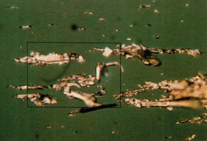
Abrasive wear particles are usually created when a rough, sharp particle is cut or when extreme sliding occurs. A bearing misalignment or asperity of a harder metal part can cause two-body abrasive wear, allowing gouging of the opposing rotating softer metal. Foreign particles in the oil also cause three-body abrasive wear. The tougher dirt particle embeds itself in a softer metal, gouging away at the spinning component’s metal.
Cutting wear particles can be long and curly due to abrasive contamination, with length-to-width ratios varying from 5-to-1 to 50-to-1. Sand or dirt are examples of abrasive particles. These sand and dirt particles typically get into the system through a faulty breather element or by seals, O-rings, and gaskets.
Erosive Wear
The loss of material caused by the repetitive impact of hard particles at a high velocity produces erosive wear particles. It affects the degree of erosion’s velocity, inclination angle, particle form, and concentration. Pumps, valves, nozzles, and even elbows are all affected.
Cavitation
Cavitation is the process of removing material from a metal surface by repeatedly imploding bubbles around or on it. When the material is removed, the bubbles emit violent shockwaves that fatigue the surface. Pumps and journal bearings are examples of this.
Polishing
The continuous removal of material from one or more surfaces by very fine abrasive particles is known as polishing. It produces a gleaming, mirror-like finish. The groove (or scratch) created by the abrasive is usually 5 to 10% of the grit diameter in width.
B. Sliding, Rolling, Impact Wear
Adhesive Wear
- Occurs when metal-to-metal contact happens at high speeds, temperatures, and loads.
- The metal “welds” together at the point of contact, creating uneven metal chunks on the surface.
- In mild cases, it’s known as “frosting” and isn’t a major problem.
- In severe cases, it can remove a significant amount of material and is also referred to as “sliding wear” or “galling”.
Spalling or Fatigue Wear
- This type of wear typically occurs on rolling contact surfaces, where the greatest sheer stresses are present.
- Caused by excessive loading or contamination.
- Leads to the formation of a pit or dent on the surface, known as a spall.
C. Chemical Wear
Corrosive Wear
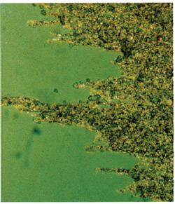
Corrosive wear is caused by an acidic assault on the internal surfaces of the machinery. It produces a layer of corrosion materials, which is removed by the sliding action. The particles are usually less than one micron in size. It can position itself on the ferrogram’s outside edges. The wear pattern on the surface is normally even and consistent.
Have questions or need assistance? Contact us today and let our experts help you find the right solutions for your needs!